Difference between revisions of "Evalkits"
(→Requirements) |
(→Single Channel) |
||
| Line 47: | Line 47: | ||
|} --> | |} --> | ||
| − | = | + | = Requirements = |
| + | |||
| + | == SiRad Easy® == | ||
| − | |||
| − | |||
| − | |||
{| | {| | ||
[[File:Easy with lens.jpg|border|right|250px|link={{filepath:{{PAGENAME:Media:Easy with lens.jpg}}}}]] | [[File:Easy with lens.jpg|border|right|250px|link={{filepath:{{PAGENAME:Media:Easy with lens.jpg}}}}]] | ||
| Line 60: | Line 59: | ||
*USB cable mini to type A | *USB cable mini to type A | ||
| − | == SiRad Simple® | + | == SiRad Simple® == |
| − | |||
| − | |||
*MS Windows 10 | *MS Windows 10 | ||
Revision as of 13:58, 12 March 2021

Contents
1 Requirements
1.1 SiRad Easy®
- MS Windows 10
- Software Package by Silicon Radar from [1]
- USB cable mini to type A
1.2 SiRad Simple®
- MS Windows 10
- Software Package by Silicon Radar from [2]
- Serial-FTDI to USB cable or adapter
2 Hardware
- Schematics [3]
- SiRad Easy 60 GHz Front End Board
- SiRad Easy 120 GHz Wideband Front End Board
- SiRad Easy 300 GHz Front End Board
2.1 Hardware Setup
2.1.1 Changing the Radar Front End
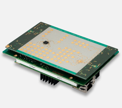
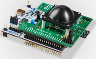
The SiRad Easy® Evaluation Kit consists of two radar front ends (24 GHz and 122 GHz), an evaluation baseband board, and an ST Microelectronics Nucleo64 microcontroller board that is stackable. Silicon Radar delivers the Evaluation Kit in the 122 GHz configuration without the lens assembled. Follow the instructions below for changing the Evaluation Kit configuration.
Disassembly
- Disconnect the USB cable from the Evaluation Kit.
- Remove the radar front end from the baseband board. Grab the short edges and pull it straight out of its connections. Do not tilt or bend the front end.
- Not recommended unless the baseband board or the microcontroller board must be replaced: Remove the baseband board from the microcontroller board by grabbing the short edges and pulling it straight out of its connections. Do not tilt or bend the baseband board.
Assembly
- If you need to connect the baseband board to the microcontroller board, first look for any bend connectors. Pull them straight before trying to connect the boards. Connect the baseband board to the microcontroller board by placing them on top of each other and matching the connectors. The WiFi module should point away from the USB connector of the microcontroller board. Now slightly press them together alternately on both sides until both boards are fully connected. Improper connection may cause shortcuts and destroy the boards
- The radar front end has to be attached to the baseband board from the top side (where the LEDs are located). It can only be connected in one way since the headers are different. Improper connection may cause shortcuts and destroy the boards.
2.1.2 Understanding the External Header (J1)
The external header in Figure 2 is used to connect to the sensor board in different operating modes. In WiFi mode, the external header is used to connect the WiFi module to the microcontroller on the board. The wireless data connection setup via WiFi is explained in Section 2.1.4. In programming mode, the external header is used to program either the WiFi module or the microcontroller, please see Section 5. The external header can also be used to trigger measurements manually via the external trigger line (TR), also see Section 3.2.3.1.
2.1.3 Data Connection via USB Cable (USB Mode)
Put the jumper JP5 on the microcontroller board in the U5V setting as shown in Figure 5 (left). Remove all jumpers from the external header on the baseband board shown in Figure 5 (middle). Bring the WiFi switch SW1 on the baseband board in the OFF position as shown in Figure 5 (right). The Evaluation Kit can now be connected to a PC using a USB cable. We recommend using an active USB Hub between the PC and the Evaluation Kit, especially when connected to a Laptop. Alternatively, the board can be powered by a standard 5V supply via the external header (pins 5V and any of the four GD pins). Please proceed to Section 2.1.5 to install the lens (optional) or to Section 2.2 for running the Evaluation Kit software.
2.1.4 Wireless Data Connection via WiFi (WiFi Mode)
Put the jumper JP5 on the microcontroller board in the E5V setting as shown in Figure 6 (left). Use the jumpers delivered with the Evaluation Kit and connect MT/WR and MR/WT on the baseband board as shown in Figure 6 (middle). Apply power from a standard source: +5V to the 5V pin and GND to any GD pin (there are four) of the external header (J1). Bring the WiFi switch SW1 on the baseband board in the ON position as shown in Figure 6 (right). Please proceed to Section 2.1.5 to install the lens (optional) or to Section 2.2 for running the Evaluation Kit software
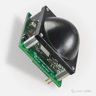
2.1.5 Mounting the Lens (Optional)
Please see lens datasheet [4] for SiRad Easy® and SiRad Simple® for more information.
3 Software/Firmware
3.1 Firmware
If you have any question about how to update and flash firmware please see the below links:
For detailed information about SiRad EvalKit Output Modes, please see this site:
How to tune and speed up the SiRad Evaluation kit, please visit:
3.2 Software Installation
3.2.1 Software Requirements
There are two options to connect the Evaluation Kit software, either using the USB connection provided by a virtual COM port or via WiFi. The hardware setup for the UART and WiFi connection modes have been explained in User Guide in Customer Download Area.
3.2.2 Connecting to the Board via WiFi
SiRad Easy®
Please be aware that the WiFi module has a limited transfer rate. The maximum possible frame update rate is about 10 Hz when using the WiFi connection. Once you power-up the SiRad Easy® in WiFi configuration, the WiFi module’s LED is flashing in blue. The WiFi module opens its own access point. This may last approximately 40 seconds. Please set the WiFi module of your PC to use automatic IP address selection via DHCP to get an IP address from the SiRad Easy®. If your PC’s WiFi module uses a static IP, it might not be possible to connect to the WiFi module of the SiRad Easy®. Connect to the SiRad Easy®’s WiFi access point using the following login credentials:
SSID: EasyRadar Password: Greetings
Once the SiRad Easy®’s WiFi module has opened an access point, it waits for approximately 40 seconds until it starts the sensor operation and the blue LED is switched off. On Windows, the IP address that was assigned by the SiRad Easy®’s WiFi module to your PC can be checked in the network manager.
SiRad Simple®
Please be aware that the WiFi module has a limited transfer rate. The maximum possible frame update rate is about 10 Hz when using the WiFi connection. Once you power-up the sensor module in WiFi configuration, the WiFi module’s LED is flashing in blue. The WiFi module opens its own access point. This may last approximately 40 seconds. Please set the WiFi module of your PC to use automatic IP address selection via DHCP to get an IP address from the sensor. If your PC’s WiFi module uses a static IP, it might not be possible to connect to the WiFi module of the sensor. Connect to the sensor’s WiFi access point using the following login credentials:
           SSID:  SimpleRadar-<uuid>		                                       Password:  SimpleRadar
                             or
           SSID:  EasyRadar				                               Password:  Greetings
Once the sensor’s WiFi module has opened an access point, it waits for approximately 40 seconds until it starts the sensor operation and the blue LED is switched off. On Windows, the IP address that was assigned by the sensor’s WiFi module to your PC can be checked in the network manager.
Please see Evalkits #Software section to find detailed information about how to connect EvalKit ( Silicon Radar WebGUI or terminal program). If you want to proceed with Silicon Radar WebGUI, you can consider Evalkits #WebGUI section or if you want to continue with a terminal program you can follow Evalkits #Terminal Program.
WiFi only: If you are using a WiFi connection to connect to the Evaluation Kit, unfold the ‘COM’ section in the control panel on the left side of the WebGUI. Provide the IP address and the port of the WiFi module of the SiRad Easy® you want to connect to before you proceed, like so: ‘192.168.4.1:9090’. The standard port is 9090. Click the ‘Connect’ button on the top left to connect to the WebSocket provided by the COM2WebSocket tool or to the WiFi module of the Evaluation Kit. The WebGUI should display the sensor data.
3.3 WebGUI
The SiRad Evaluation Kit is developed to demonstrate the functionality of Silicon Radar’s transceiver chips as millimeter-wave distance and velocity sensor front ends.
*WebGUI
3.4 Terminal Program
You can use a terminal program to send the command strings and log measurement data, for more information :
3.5 Octave / Matlab
Can you help me to set up the device for the use with MATLAB / Octave?
A description of how you can set up and import raw ADC data into MATLAB / Octave can be found here:
3.6 C Library
We provide example C source code files for our Evalkit Sirad Easy to help you develop your own application includes project and small example application and driver files for ADC, PLL, radar front end, baseband board, and more, development environment (needed tools): System Workbench (Eclipse) by ST, STM32CubeMX by ST, F3 v1.9.0 MCU package for STM32CubeMX by ST. Please visit our Customer Download Area.
4 FAQ
Not able to find your problem here or your problem not solved by above suggestions? We strongly suggest you read the FAQs, Protocol Description, and User Guides (in the download area) as they can be the answer to most of your questions.