Output Modes 1.4
Contents
Supported Protocols
The SiRad Evaluation Kit communicates via UART. The UART protocol is (extended) ASCII based and supports communication to any PC / microcontroller / device that supports the UART settings and that implements the communication protocol described in this document. There are three output modes (WebGUI, TSV, binary; explained below) but only one way to control the device via input commands, explained in Section Command Frames. The kit supports the Silicon Radar WebGUI for graphical control but also terminal programs, TSV output (Tab Separated Values) for import into Excel / third party software or logging to text files and binary output for faster communication to other microcontrollers or third party software. The kit always starts up with the WebGUI protocol enabled after powering. The output modes can be switched in the WebGUI or using the protocol commands described in this document from a terminal program or a third party control software. The TSV and binary output modes are not supported by the WebGUI.
UART Settings
This documents applies for firmware version 1.4 or later and is incompatible to firmware version 1.31 and below. The following UART settings apply for firmware version 1.4 and later: 1 Mbaud, 8 data bits, 1 start bit, 1 stop bit, no parity, no flow control.
Supported Data Frames per Output Mode
You can find the supported data frames by each protocol in Table 1. Data frames that are not supported by TSV or binary output modes can still be sent while using TSV or binary mode, but the data format of these frames will be in the WebGUI format.
| Data Frame | Description | WebGUI | TSV | Binary |
| ADC raw data frame | Contains ADC raw data (I/Q) | (-) | X | X |
| Range frame | Contains distance data extracted from the FFT | X | X | X |
| Phase frame | Contains phase information extracted from the FFT | X | X | X |
| CFAR frame | Contains the output of the CFAR operators | X | X | X |
| Target list frame | Contains the target list with the detected targets | X | X | X |
| Status update frame | Contains status data updates | X | X | X |
| Error info frame | Contains basic error information | X | (-) | X |
| Detailed error info frame | Contains detailed error information | X | (-) | (-) |
| System info frame | Contains hardware information | X | (-) | (-) |
| Version info frame | Contains hardware and firmware information | X | (-) | (-) |
Output Mode Configuration (Examples)
Some examples of how to change the output modes are given in the following sub sections.
Change Output Mode and Data from the WebGUI (WebGUI, TSV or Binary)
- Open the Com2WebSocket tool, select 1Mbaud, a correct comport, and connect to the kit
- Open the WebGUI and connect to the WebSocket provided by the Com2WebSocket tool
- (Optional) Set any desired RF, processing and target recognition parameters
- Change to the “Output Data” tab
- Chose the protocol type with the “Protocol Type” slider
- Select the desired output data checkboxes
From that moment on, the kit transmits the selected data frames and it can be disconnected from the WebGUI and the Com2WebSocket tool, if needed.
Change to TSV Output Mode from a Terminal Program
- Find your desired bit settings in the “System Configuration” command
- Set the “Protocol” bits in the “System Configuration” command to “001” (TSV)
- Send the command to the kit
The output should change to the desired output mode.
Change to Binary Output Mode from a Terminal Program
- Find your desired bit settings in the “System Configuration” command
- Set the “Protocol” bits in the “System Configuration” command to “010” (BIN)
- Send the command to the kit
The output should change to the desired output mode.
Activate ADC Raw Data (I/Q) Output from a Terminal Program
- Find your desired bit settings in the “System Configuration” command
- Find your desired bit settings in the “Baseband Configuration” command
To enable un-windowed ADC raw data output
- Set the “RAW” bit in the “System Configuration” command
- Unset the “WIN” bit in the “Baseband Configuration” command
To enable windowed ADC raw data output
- Set the “RAW” bit in the “System Configuration” command
- Set the “WIN” bit in the “Baseband Configuration” command
To enable/disable DC cancellation
- Set the “DC” bit in the “Baseband Configuration” command accordingly
- Then send both commands to the kit.
Activate Complex FFT Data Output from a Terminal Program
- Use calculated settings as described above
- Set the “CMP” bit in the “System Configuration” command
- Send the command to the kit
Commands (Input)
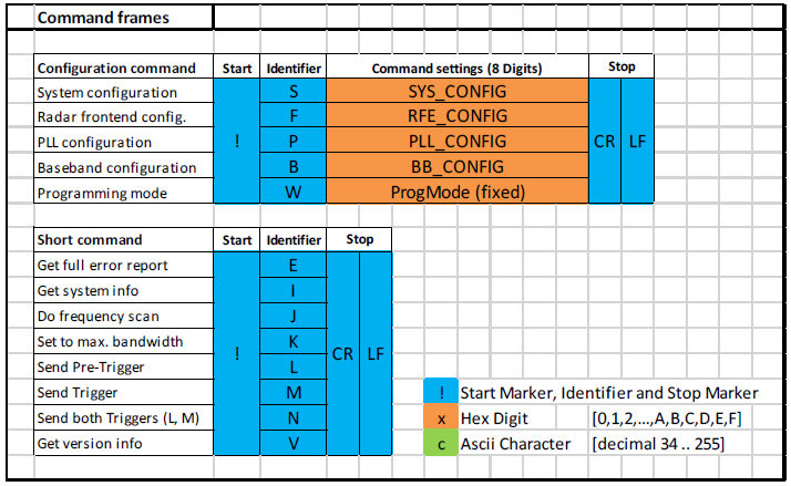
Command Frames
Each command frame starts with ASCII value 33 (‘!’) as start marker and ends with two ASCII command characters (‘CR’ and ‘LF’) as stop marker, also see the blue parts in Figure 1. Orange parts indicate data parts (explained later in this section).
Hardware and Software Compatibility
| Command Frame | Identifier | SiRad Easy® | SiRad Simple® | WebGUI |
| System configuration | S | X | X | X |
| Radar front end configuration | F | X | X | X |
| PLL configuration | P | X | X | X |
| Baseband configuration | B | X | X | X |
| Programming mode | W | (-) | X | (-) |
| Get full error report | E | X | X | X |
| Get system info | I | X | X | X |
| Do frequency scan | J | X | X | X |
| Set to max. bandwidth | K | X | X | X |
| Send Pre-Trigger | L | X | X | (-) |
| Send Trigger | M | X | X | (-) |
| Send both Triggers (L, M) | N | X | X | (-) |
| Get version info | V | X | X | X |
Configuration (Long) Commands
The commands in Table 3 contain data for the configuration of the kit and are explained in the following sections. The configuration commands are available in all output modes.
| Command Frame | Identifier | Answer | Description |
| System configuration | S | X | Configure basic functions of the system |
| Radar front end configuration | F | X | Configure front end base-frequency |
| PLL configuration | P | X | Configure the bandwidth of the frequency ramp |
| Baseband configuration | B | X | Configure baseband and processing related parameters |
| Programming mode | W | (-) | Used to flash SiRad Simple® without hardware configuration |
System Configuration
The system configuration command configures basic functions of the system, including triggering, LED, data output, and gain. When the ERR, ST, TL, P, C, R, CPL, or RAW bits are enabled, the according frame will be output after each measurement. Use these bits to switch the transmission of these frames on or off. Switching unnecessary frames off can increase the update rate of the device significantly.

| Format Field | Field Size | Description |
| SelfTrigDelay | 3 bits | Sets a delay time between self-trigger events |
| LOG | 1 bit | Sets scaling type of magnitude data; when set to 0, magnitude data is in dB; linear scaled magnitude outputs are ONLY useful for TSV or binary output format |
| FMT | 1 bit | Select the data output format: mm / cm |
| LED | 2 bits | When set to 1st target rainbow, the LED displays the distance of the first recognized target as a color from blue (far) over green (medium range) to red (close). The current maximum range is used as a reference. |
| Protocol | 3 bits | Protocol type for data output: WebGUI, TSV (tab separated values) and binary; TSV and binary outputs are NOT displayed in the WebGUI |
| AGC | 1 bit | Auto Gain Control mode: overrides the manual settings in the ‘Gain’ field. Uses 2 ramps at the beginning of the measurement or the pre-trigger phase for gain measurement (depending on whether ‘Pre-trigger’ is switched on). |
| Gain | 2 bits | Manual gain setting. Overridden by the AGC bit, which enables Auto Gain Control. |
| SER1 | 1 bit | UART-USB connection on the Simple, WIFI or header bar on the SiRad Easy® |
| SER2 | 1 bit | USB connection on SiRad Easy®; configuration data can be fed to the device using both UARTs at any time |
| ERR | 1 bit | Enables the Error Information frame |
| ST | 1 bit | Enables the Status Information frame |
| TL | 1 bit | Enables the Target List frame |
| P | 1 bit | Enables the Phase frame |
| C | 1 bit | Enables the CFAR frame |
| R | 1 bit | Enables the Magnitude / Range frame |
| CPL | 1 bit | Enables the Complex FFT data frame; NOT displayed in the WebGUI |
| RAW | 1 bit | Enables the ADC raw data (I/Q) frame; NOT displayed in the WebGUI |
| PRE | 1 bit | Enable pre-trigger (applies only in manual trigger mode) |
| SLF | 1 bit | Switch between self-trigger and manual trigger |
Default Settings
Below you can find the default settings of the WebGUI for the SYS_CONFIG command frame to speed up your development by simple copy and paste into your favorite terminal program.
| SYS_CONFIG command for device | Resulting command |
| SiRad Easy® | !S01012F82 |
| SiRad Simple® 120 GHz | !S01011F82 |
Radar Frontend Configuration
The radar front end configuration command configures the start (or base) frequency for the front end. The base frequency can be set in 250 kHz steps. Each front end has a slightly different minimum and maximum operating frequency due to production tolerances. The SiRad Simple® has a fixed 122 GHz front end onboard.

RF Base-Frequency (21 bit)
The base-frequency is a 21-bit unsigned integer value interpreted in MHz, so the theoretic value range is 0 to 524287 MHz in 250 kHz steps. Please note, that each frontend has a slightly different minimum and maximum operating frequency due to production tolerances. The frequencies supported by your frontend should be approximately in the range of 23300 to 26200 MHz for the 24 GHz frontend and 119100 to 125900 MHz for the 122 GHz frontend. The base-frequency should be chosen at least 100 MHz above the minimum operating frequency. The base-frequency plus the chosen bandwidth should not exceed the maximum operating frequency minus 100 MHz for an unsaturated signal. For example to set 122 GHz as base frequency, 77240xh should be assigned.
Default Settings
Below you can find the default settings of the WebGUI for the RFE_CONFIG command frame to speed up your development by simple copy and paste into your favorite terminal program.
| RFE_CONFIG command for device | Base Frequency | Resulting Command |
| SiRad Easy® 120 GHz | 120000 MHz | !F00075300 |
| SiRad Easy® 24 GHz | 24000 MHz | !F00017700 |
| SiRad Simple® 120 GHz | 120000 MHz | !F00075300 |
PLL Configuration
The PLL configuration command in Figure 6 is used to configure the bandwidth of the frequency ramp.

Bandwidth (16 bit)
The bandwidth word is a signed 16-bit value interpreted in MHz, so the theoretic value range is -65536 to +65534 MHz in 2 MHz steps. Negative values result in a falling ramp slope, positive value provide a rising saw tooth shape. Representation is in two‘s complement.
Please note that the maximum bandwidth supported by the 24 GHz frontend is around 3000 MHz. For the maximum bandwidth of the 122 GHz frontend, please see the data sheet (> 6000 MHz).
Default Settings
Below you can find the default settings of the WebGUI for the PLL_CONFIG command frame to speed up your development by simple copy and paste into your favorite terminal program.
| PLL_CONFIG command for device | Bandwidth | Resulting Command |
| SiRad Easy® 120 GHz | 5000 MHz | !P000009C4 |
| SiRad Easy® 24 GHz | 1000 MHz | !P000001F4 |
| SiRad Simple® 120 GHz | 5000 MHz | !P000009C4 |
| PLL_CONFIG command for device | Bandwidth | Resulting Command |
| TRX_024_006 | 3000 MHz | !P000005DC |
| TRX_024_007 | 3000 MHz | !P000005DC |
| TRM_060_039 | 7000 MHz | !P00000DAC |
| TRX_120_001 | 6000 MHz | !P00000BB8 |
| TRA_120_002 | 6000 MHz | !P00000BB8 |
| TRA_120_012/031 | 24000 MHz | !P00002EE0 |
| TRA_300_030 | 40000 MHz | !P00004E20 |
Baseband Setup
The baseband configuration command in Figure 8 is used to configure baseband and processing related parameters, like CFAR parameters, FFT parameters and sampling parameters.

WIN (1 bit) - Windowing (Supported by WebGUI)
Apply windowing is on the samples before performing FFT. Enabled by default
FIR (1 bit) – FIR Filter (Supported by WebGUI)
Activates FIR filter, disabled by default.
DC (1 bit) - DC Cancellation (Supported by WebGUI)
Activates de-trending and static offset compensation in the digital domain.
CFAR Parameters
The constant false alarm rate (CFAR) operator is used to calculate an adaptive threshold above the noise floor. Due to the characteristics of usual target spectra it can be used as an efficient way to achieve a guaranteed detection threshold and reduce false alarms. However, the CFAR operator might not be ideal in every target situation or for every application. It should also be optimized for the specific measurement task. The default CFAR implementation is the standard cell-averaging (CA-CFAR) approach. The operator is slid through the sample buffer, calculating each cell under test separately. The cell under test is ignored, as well as the number of guard cells left and right of the cell under test. The number of cells left and right of the guard interval are then used to calculate the noise floor around the cell under test. The threshold value is then added to this average. Due to this approach, the contrast around a clean target is increased. There are, however, situations where the CA-CFAR operator does not achieve sufficient results. This is the case when there are many targets in similar distances. The targets will be treated as noise and may not be detected in such cases. The number of targets in adjacent range cells should therefore not exceed the guard interval value to achieve good results.
CFAR Type (2 bit) (Supported by WebGUI)
Select CFAR operator mode. By default CA-CFAR operator is chosen.
CFAR Threshold (4 bit)(Supported by WebGUI)
CFAR threshold value added to the average of the CA-CFAR operator. The CFAR threshold is a
4 bit unsigned integer value with a value range of 0 to 30 in step size of 2.
CFAR Size (4 bit)(Supported by WebGUI)
The number of cells left and right of the CA-CFAR guard interval are then used to calculate the noise floor around the cell under test. The CFAR size is a 4 bit unsigned integer value with a value range of 0 to 15.
CFAR Grd (2 bit)(Supported by WebGUI)
The CFAR guard number is the number of guard cells left and right of the cell under test that are ignored for the CA-CFAR calculation. The CFAR guard is a 2 bit unsigned integer value with a value range of 0 to 3.
FFT Parameters
Average N (2 bit) (Supported by WebGUI)
Average N is a 2 bit unsigned integer value from 0 to 3 interpreted as an average of 1 to 4 elements. Average N configures the averaging filter at the output of the FFT calculation. The filter is calculated using the following formula, where x is the sample number:
FFT Size (3 bit)(Supported by WebGUI)
Configures the number of FFT points from 32 to 2048. The FFT size is a 3 bit unsigned integer value. The value range is 0 to 7, interpreted as 2 to the power of (’FFT Size’ + 5). For example, ‘FFT size’ = 0 is interpreted as 2^(0+5) = 32, ‘FFT size’ = 5 is interpreted as 2^(5+5) = 1024.
Downsampling (3 bit)(Supported by WebGUI)
The downsampling factor is used to decrease the number of samples for the FFT. ‘Downsampling’ is a 3 bit unsigned integer value. The value range is 0 to 7, interpreted as 0 for the value 0 and 2 to the power of (’Downsampling’ – 1) for the values 1 to 7. For example, ‘Downsampling’ = 0 is interpreted as 0, ‘Downsampling’ = 1 is interpreted as 2^(1-1) = 1, ‘Downsampling’ = 7 is interpreted as 2^(7-1) = 64.
A downsampling factor of one will result in half the number of samples, a factor of two in a quarter of the number of samples and so on. To achieve this, each number of ‘Downsampling’ samples are averaged and the remaining sample positions in the sample buffer are zero-padded like in
Figure 19.

ADC Sampling Parameters
Ramps - Number of Ramps
‘#Ramps’ determines the number of ramps that are used for every measurement after the pre- measurement phase. ‘#Ramps’ is a 3 bit unsigned integer value. The value range is 0 to 7, interpreted as 2 to the power of ’#Ramps’. For example, ’#Ramps’ = 0 is interpreted as 2^0 = 1, ’#Ramps’ = 7 is interpreted as 2^7 = 128.
Setting this value to 4 will result in 6 ramps chirped for each measurement. 2 ramps are taken as pre-measurement for the automatic gain detection and 4 ramps will be A/D converted and sample-wise added before the FFT is calculated.
Samples - Number of Samples
‘#Samples’ is the number of samples taken per ramp. The number of samples is a 3 bit unsigned integer value. The value range is 0 to 7, interpreted as 2 to the power of (‘#Samples’ + 5).
For example, ‘#Samples’ = 0 is interpreted as 2^(0+5) = 32, ‘#Samples’ = 5 is interpreted as
2^(5+5) = 1024.
Increase this number to achieve better resolution and to get longer ramp times. The ramp time is rounded to microsecond resolution. The ramp time is calculated using the following formula: Tramp = Nsamples/Fadc
ADC ClkDiv - ADC clock divider / Sample frequency
‘ADC ClkDiv’ determines the ADC clock divider setting. ‘ADC ClkDiv’ is a 3 bit unsigned integer value. The value range is 0 to 7, according to the index of an internal look-up table which leads to the given number of MS/s according to the ‘ADC ClkDiv’ table in Figure 18.
Higher values result in longer A/D conversion times and thus longer ramp times and can increase the signal strength of low signals.
Default Settings
Below you can find the default settings of the WebGUI for the PLL_CONFIG command frame to speed up your development by simple copy and paste into your favourite terminal program.
| BB_CONFIG command for device | Resulting Command |
| SiRad Easy® 120 GHz | !P000009C4 |
| SiRad Easy® 24 GHz | !P000001F4 |
| SiRad Simple® 120 GHz | !P000009C4 |
Special Function Commands
Certain commands, explained in this section, use only a single letter to execute a function very fast. Send these commands three times in a row in case they are not executed.
Get fill error info - !E
Request a detailed error info frame at the next transmission slot.
Get system info - !I
Request a system info frame at the next transmission slot.
Do frequency scan - !J
The system scans the maximum usable bandwidth of the installed frontend at every startup. To trigger that scan manually at runtime, use this command.
Set to max. bandwidth - !K
Set the ramp bandwidth to the previously measured maximum.
Send Pre-Trigger - !L
Software command to trigger the pre-measurement. The pre-measurement consists of 2 ramps which are used to evaluate the maximum usable baseband gain by the Auto Gain Control (AGC) Mode feature. It is executed before each measurement. If the Pre-trigger bit in the SYS_CONFIG register is set and the Self-trigger bit is reset, the system waits for an external Pre-trigger and trigger either on the hardware trigger line or this software command.
Send Trigger - !M
Software command to trigger a measurement. Execute this command max. 40 ms after the Pre-trigger, or the system will go back to idle.
Send Pre-Trigger+Trigger - !N
Software command to send a Pre-trigger (!L) and a trigger (!M) all in one command.
Get version info - !V
Request a version info frame at the next transmission slot.
Timing and UART Receive Buffer
There are no timing constraints when sending commands to the kits, however, the UART receive buffer in the kits has a limited size of 128 bytes, which limits the number of commands that can be send in a row. This has to be taken into consideration when sending commands to the kits. Commands are processed after each measurement cycle. If multiple commands need to be sent in a row and their total size exceeds 128 bytes, they have to be split and a part of them has to be sent after the next measurement cycle.
WebGUI Output Mode (Default)
Once the SiRad Evaluation Kit is plugged in, it begins sending standard data. The standard data is transmitted in blocks of different data frames that are tied together in a single transmission, as highlighted in Figure 11. In the figure, two data blocks are marked red. Each data block ends with ASCII value 32 (‘ ‘, space) as stop marker and can contain multiple data frames of different size. In the example in Figure 11, the data locks contain 5 data frames each. One data frame in the upper block is marked blue. Each data frame starts with ASCII value 33 (‘!’) as start marker and ends with two ASCII command characters (‘CR’ and ‘LF’) as stop marker.

Figure 12 shows the supported standard data frames and Table 1 lists their purpose. The blue parts in Figure 12 indicate start and stop markers and the frame identifier, orange and green parts indicate data parts and grey parts indicate reserved parts that should not be used.

There are several frame types that consist of multiple data values tied together to form a specific data packet, for example, a frame containing detected targets or a frame containing system information. Each frame type is recognized by a unique identifier (a certain letter) following the start marker of the frame, for example, the letter ‘T’ indicates a frame containing target data (the list of detected targets) or ‘I’ indicates a frame containing system information. The frame types are of different size. Please read the following sections about how to interpret the transmitted data in the frames.

Magnitude/Range, Phase and CFAR Output
The range frame contains the magnitude output of the FFT and the phase frame contains the argument of the FFT. The CFAR frame contains the output of the CFAR operator that is used to detect targets. The range frame, phase frame and CFAR frame share the same frame format, please see Figure 13. The start and stop markers and frame identifiers are highlighted in blue, data parts in orange and green color, reserved parts with grey stripes.
After the frame’s start marker (1 byte) and identifier ‘R’, ‘P’ or ‘C’ (1 byte) follows a 4 bytes ‘Size’ field, which indicates the number of data points (bytes) in the ‘Data’ field of the frame. There are two reserved fields of 4 bytes size between the ‘Size’ and the ‘Data’ field. The frame ends with the stop markers ‘CR’ + ‘LF’.
Size field
The ‘Size’ field is encoded as a 16 bit unsigned HEX number in 4 transmitted bytes (marked with 4
‘x’ in Figure 13). The data is recognized as ‘0000’ to ‘FFFF’ characters in the terminal output, and is
interpreted as values between 0 and 65535, also see Table 11. For example, ‘Size’ = 0200 is
interpreted as 0x0200, which is 512 in decimal range.
Please note, that this field is dependent on the chosen FFT size. However, a certain FFT size will
lead to a half of the size of the FFT in the ‘Size’ field only. The FFT output is mirrored along the
magnitude axis, so both parts are added together before the transmission and the length of the
transmitted data is only half of the FFT output.

Data field
The ‘Data’ field contains either the FFT output’s magnitude (distance) data, the argument (phase)
data or the CFAR output data, depending on the frame type.
The range and CFAR frame ‘Data’ bytes are transmitted as characters (marked with letters ‘c’ in
Figure 13). The data is recognized as characters of decimal value 34 to 254 in the terminal output,
and is interpreted as values between -140 and +80 dB in 220 steps of 1 dB, also see Table 11. For
example, ‘Data’ = ’Z’ is decimal 90 and means -84 dB.
The phase frame ‘Data’ bytes are transmitted as characters (marked with letters ‘c’ in Figure 13).
The data is recognized as characters of decimal value 34 to 254 in the terminal output, and is
interpreted as values between –π to +π in 220 steps, also see Table 11. For example, ‘Data’ = ’Z’ is
decimal 90 and means -1.54 rad (which is -88.36°).
Target Information
The target list contains the targets recognized by the CFAR operator. A target is detected whenever the magnitude of the FFT exceeds the CFAR operator’s threshold. The local maximum of that area is marked as a target. The target list’s frame format is shown in Figure 14.
The target list frame begins with the start marker (1 byte) and the identifier ‘T’ (1 byte) followed by the ‘Format’ field (1 byte), which indicates the unit format of the values in the ‘Distance’ field, and a ‘Gain’ value (1 byte) for the measurement. Then follows the target List with the target information, which is repeated 16 times (for 16 targets) and consists of a ‘Target #’ number (1 byte), the ‘Distance’ to the target (4 bytes), the ‘Magnitude’ or the signal strength of the target (1 byte), the argument or ‘Phase’ information of the target (4 bytes), and a reserved field (4 byte). The frame ends with the stop markers ‘CR’ + ‘LF’.
Format field
The ‘Format’ field is encoded as an unsigned HEX digit in 1 transmitted byte (marked with an ‘x’ ). The data is recognized as a ‘0’ to ‘F’ character in the terminal output, and is interpreted as a value between 0 and 15, also see Table 12. For example, ‘Format’ = 1 is interpreted as 0x1, which is 1 in decimal range. Please see Table 13 and 14 for the meaning of the values in the ‘Format’ field.

Gain field
The ‘Gain’ field is transmitted as a character (marked with a ‘c’ in Figure 13). The data is recognized
as a character of decimal value 34 to 254 in the terminal output, and is interpreted as a value
between -140 and +80 dB in 220 steps of 1 dB, also see Table 3. For example, ‘Gain’ = ’Z’ is
decimal 90 and means -84 dB. There are currently four fixed gain settings available that depend on
the hardware version, see Table 14.

Target list
The target information is repeated 16 times in the target list. All 16 target information blocks are
sent, regardless whether the target blocks are filled with detected targets or not. Empty target
information blocks of the list are filled with zeros. Each target information block consists of the
‘Target #’, ‘Distance’, ‘Magnitude’, and ‘Phase’ fields.
Target field
The ‘Target #’ number field is encoded as an unsigned HEX digit in 1 transmitted byte (marked with
an ‘x’ in Figure 14). The data is recognized as a ‘0’ to ‘F’ character in the terminal output, and is
interpreted as a value between 0 and 15, also see Table 15. For example, ‘Target #’ = F is
interpreted as 0xF, which is 15 in decimal range.
Distance field
The ‘Distance’ field is encoded as a 16 bit unsigned HEX number in 4 transmitted bytes (marked
with ‘x’ in Figure 14). The data is recognized as ‘0000’ to ‘FFFF’ characters in the terminal output,
and is interpreted as values between 0 and 65535, also see Table 15. For example, ‘Distance’ =
0200 is interpreted as 0x0200, which is 512 in decimal range. The unit of the distance is
determined by the value in the ‘Format’ field.
Magnitude field
The ‘Magnitude’ field is transmitted as a character (marked with a ‘c’ in Figure 14). The data is
recognized as a character of decimal value 34 to 254 in the terminal output, and is interpreted as a
value between -140 and +80 dB in 220 steps of 1 dB, also see Table 15. For example,
‘Magnitude’ = ’Z’ is decimal 90 and means -84 dB.
Phase field
The ‘Phase’ field is encoded as a 16 bit unsigned HEX number in 4 transmitted bytes (marked with
‘x’ in Figure 14). The data is recognized as ‘0000’ to ‘FFFF’ characters in the terminal output, and is
interpreted as values between -32768…+32767, also see Table 15.
Status Information
The status update frame in Figure 15 is a feedback of the current accuracy, range, ramp time, and ramp bandwidth and also returns the time since the last measurement.
The status update frame begins with the start marker (1 byte) and the identifier ‘U’ (1 byte) followed by the ‘Format’ field (1 byte), which indicates the unit format of the values in the ‘Max. Range’ field, and a ‘Gain’ value (1 byte) for the last measurement. Then follows the ‘Accuracy’ field (4 byte) currently configured settings, the ‘Max Range’ field (4 bytes) with the maximum detectable range with the current settings, the currently used ‘Ramp time’ (4 byte), the ‘Bandwidth’ field (4 bytes), and the time passed since the last measurement in the ‘Time diff.’ field (4 byte). The frame ends with the stop markers ‘CR’ + ‘LF’.

Format field
The ‘Format’ field is encoded as an unsigned HEX digit in 1 transmitted byte (marked with an ‘x’ in Figure 15). The data is recognized as a ‘0’ to ‘F’ character in the terminal output, and is interpreted as a value between 0 and 15, also see Table 7. For example, ‘Format’ = 1 is interpreted as 0x1, which is 1 in decimal range. Please see Table 13 for the meaning of the values in the ‘Format’ field.
Gain field
The ‘Gain’ field is transmitted as a character (marked with a ‘c’ in Figure 15). The data is recognized as a character of decimal value 34 to 254 in the terminal output, and is interpreted as a value between -140 and +80 dB in 220 steps of 1 dB, also see Table 16. For example, ‘Gain’ = ’Z’ is decimal 90 and means -84 dB. There are currently four fixed gain settings available that depend on the hardware version, see Table 14.
Accuracy field
The ‘Accuracy’ field is encoded as a 16 bit unsigned HEX number in 4 transmitted bytes (marked with ‘x’ in Figure 15). The data is recognized as ‘0000’ to ‘FFFF’ characters in the terminal output, and are interpreted as values between 0 to 65535, which are translated to an accuracy of 0 to 6553.5 mm with 0.1 mm resolution, also see Table 16. For example, ‘Accuracy’ = 0200 is interpreted as 0x0200, which is 512 in decimal range and translates to an accuracy of 51.2 mm.

Max. Range field
The ‘Max. Range’ field is encoded as a 16 bit unsigned HEX number in 4 transmitted bytes (marked with ‘x’ in Figure 15). The data is recognized as ‘0000’ to ‘FFFF’ characters in the terminal output, and are interpreted as values between 0 and 65535 in the chosen distance unit, also see Table 17. For example, ‘Max. Range’ = 0200 is interpreted as 0x0200, which is 512 in decimal range. The unit of the distance is determined by the value in the ‘Format’ field.
Ramp time field
The ‘Ramp time’ field is encoded as a 16 bit unsigned HEX number in 4 transmitted bytes (marked
with ‘x’ in Figure 15). The data is recognized as ‘0000’ to ‘FFFF’ characters in the terminal output,
and are interpreted as values between 0 to 65535 in us, also see Table 8 For example,
‘Ramp time’ = 0200 is interpreted as 0x0200, which is 512 in decimal range.
Bandwidth field
The ‘Bandwidth’ field is encoded as a 16 bit unsigned HEX number in 4 transmitted bytes (marked with ‘x’ in Figure 15). The data is recognized as ‘0000’ to ‘FFFF’ characters in the terminal output, and are interpreted as values between -65536 and 65534 in MHz in 2MHz steps, also see Table 17. For example, ‘Bandwidth’ = 0200 is interpreted as 0x0200, which is 1024 in decimal range and the data is in two's complement.
Time diff. field
The ‘Time diff.’ field is encoded as a 16 bit unsigned HEX number in 4 transmitted bytes (marked
with ‘x’ in Figure 15). The data is recognized as ‘0000’ to ‘FFFF’ characters in the terminal output,
and are interpreted as values between 0 to 65535, which translates to 0 to 0.65535 seconds in
10 ms steps, also see Table 8. For example, ‘Time diff.’ = 0200 is interpreted as 0x0200, which is
512 in decimal range. The counter runs at 100 kHz and is configured as an overflowing 16-bit
counter. Each tick lasts 10 ms and the counter overflows at 0.65535 seconds. Therefore, the
minimum unambiguous measurement frequency is 1.5 Hz.
Version Information
The version frame is used to uniquely identify the SiRad Evaluation Kit and returns information about the hardware and firmware, see Figure 16.
Length field
Contains the length of the version frame excluding the start marker, identifier, the length field itself
and the stop markers. Field size: 4 hex chars.
UID tag (‘U’)
Indicates the start of the UID field. Size: 1 hex char.
‘U’ len L1
Contains the length of the UID field (number of chars). Field size: 2 hex chars.
UID (L1) field
The ‘Microcontroller UID’ field is a unique 24 byte unsigned HEX number, also see Table 9. Field size: variable.
HW tag (‘H’)
Indicates the start of the HW field. Size: 1 hex char.
‘H’ len L2
Contains the length of the HW field (number of chars). Field size: 2 hex chars.
HW (L2) field
Contains the baseboard hardware identifier, for example, ‘EA’ for the SiRad Easy or ‘SI’ for the SiRad Simple. Field size: variable.
PLL tag (‘P’)
Indicates the start of the PLL field. Size: 1 hex char.
‘P’ len L3
Contains the length of the PLL field (number of chars). Field size: 2 hex chars.
PLL (L3) field
Contains the PLL chip identifier, for example, ‘59’ for the ADF4159. Field size: variable.
CLK tag (‘Q’)
Indicates the start of the CLK field. Size: 1 hex char.
‘Q’ len L4
Contains the length of the CLK field (number of chars). Field size: 2 hex chars.
CLK (L4) field
Contains the CLK chip identifier. Field size: variable.
ADC tag (‘A’)
Indicates the start of the ADC field. Size: 1 hex char.
‘A’ len L5
Contains the length of the ADC field (number of chars). Field size: 2 hex chars.
ADC (L5) field
Contains the operating mode of the ADC, for example, ‘I’ for interleaved mode or ‘N’ non-interleaved mode. Field size: variable.
RFE tag (‘F’)
Indicates the start of the RFE field. Size: 1 hex char.
‘F’ len L6
Contains the length of the RFE field (number of chars). Field size: 2 hex chars.
RFE (L6) field
Radar front end chip identifier of firmware
Software version tag (‘S’)
Indicates the start of the software version field. Size: 1 hex char.
‘S’ len L7
Contains the length of the software version field (number of chars). Field size: 2 hex chars.
Software version (L7) field
Contains the software version as described below. Field size: variable.
<check-in ID >-<date >-<major>.<minor>.<revision>
Communication protocol version tag (‘C’)
Indicates the start of the protocol version field. Size: 1 hex char.
‘C’ len L8
Contains the length of the protocol version field (number of chars). Field size: 2 hex chars.
Protocol version (L8) field
Contains the protocol version as described below. Field size: variable.
<protocol ID>-<spec date>-<major>.<minor>.<revision>
| RFE Field | Description |
| 024_006 | TRX_024_006 |
| 024_007 | TRX_024_007 |
| 060_039 | TRM_060_039 |
| 120_00x | TRX_120_001 / TRA_120_002 |
| 120_wid | TRA_120_012 / TRA_120_031 |
| 300_030 | TRA_300_030 |
System Information
The system info frame is used to uniquely identify different SiRad Evaluation Kits and return radar frontend information, see Figure 17.
After the start marker (1 byte) and the identifier ‘I’ (1 byte) follows the ‘UID’ field (24 bytes), which carries the UID of the microcontroller on the SiRad Evaluation Kit. Afterwards, there is a 2 byte reserved field then follow two 5 byte fields, which contain the minimum and maximum frequencies of the SiRad Evaluation Kit’s radar frontend. The frame ends with the stop markers ‘CR’ + ‘LF’.

Microcontroller UID field
The ‘Microcontroller UID’ field is a unique 24 byte unsigned HEX number (marked with ‘x’ in
Figure 17), also see Table 19.
RFE MinFreq field
The ‘RFE MinFreq’ field is encoded as a 20 bit unsigned HEX number in 5 transmitted bytes
(marked with ‘x’ in Figure 17). The data is recognized as ‘00000’ to ‘FFFFF’ characters in the
terminal output, and are interpreted as values between 0 and 1048575 in MHz, also see Table 19.
For example, ‘RFE MinFreq’ = 1D0D8 is interpreted as 0x1D0D8, which is 119000 in decimal
range.
RFE MaxFreq field
The ‘RFE MaxFreq’ field is encoded as a 20 bit unsigned HEX number in 5 transmitted bytes
(marked with ‘x’ in Figure 17). The data is recognized as ‘00000’ to ‘FFFFF’ characters in the
terminal output, and are interpreted as values between 0 and 1048575 in MHz, also see Table 19.
For example, ‘RFE MaxFreq’ = 1E848 is interpreted as 0x1E848, which is 125000 in decimal
range.
Detailed Error Information
The detailed error info frame includes error bits that may be raised during the signal processing of the radar data, see Figure 18: Detailed error information frame format. This frame can be requested by sending the !E command and will be send in addition to the basic error information frame below.
The detailed error info frame begins with the start marker (1 byte) and the identifier ‘E’ (1 byte) followed by the ‘Error flags’ field (8 byte), which is zero when no errors have been detected. The frame ends with the stop markers ‘CR’ + ‘LF’.
Error flags field
The ‘Error flags’ field is transmitted as a 8 byte unsigned HEX number (marked with ‘x’ in Figure 18).
Figure 19 shows the error bits in the ‘Error flags’ field. The error bits are explained below.

Error domains:
- CRC: <reserved>
- FLS: <reserved>
- FFT: <reserved>
- ADC: temporary ADC, sampling and data buffering errors
- AMP: temporary amplification errors, for example, saturation
- PLL: temporary PLL configuration errors, for example, operating range exceeded
- RFE: temporary radar frontend configuration errors, for example, operating range exceeded
Temporary errors are raised during processing but may go away when the parameter setting is changed. For example, when the parameters for the front end are manually changed so that its operating range is exceeded, a temporary RFE or PLL error may appear as long as this setting is applied.
Error Information
The error info frame includes error bits that may be raised during the signal processing of the radar data, see Figure 20. This frame will be send by default when the status update is enabled.
The error info frame begins with the start marker (1 byte) and the identifier ‘E’ (1 byte) followed by the ‘Error flags’ field (4 byte), which is zero when no errors have been detected. The frame ends with the stop markers ‘CR’ + ‘LF’.
Error flags field The ‘Error flags’ field is transmitted as a 4 byte unsigned HEX number (marked with ‘x’ in Figure 20). Figure 21 shows the error bits in the ‘Error flags’ field. The error bits are explained below.

Error domains:
- FLS: <reserved>
- PRC: temporary errors in the signal processing
- BB: temporary baseband processing errors
- PLL: temporary PLL configuration errors
- RFE: temporary radar frontend configuration errors
- CRC: temporary errors in the UART transmission or CRC checksum
Temporary errors are raised during processing but may go away when the parameter setting is
changed. For example, when the parameters for the front end are manually changed so that its
operating range is exceeded, a temporary RFE or PLL error may appear as long as this setting is
applied.
TSV Format
Figure 22 shows the supported TSV output frames and Table 20 lists their purpose. The TSV protocol has a limited set of data frames. When the TSV output is activated, the data is in decimal range. Therefore, the TSV data frames can be configured to transmit the raw data of the ADC. The blue parts in Figure 22 indicate start and stop markers, frame identifiers and delimiters as well as signs, yellow indicates data parts with string numbers of variable length. The WebGUI output frames for the version info (!V), system info (!I), and the error frames (!E), can be used together with the TSV output mode but there is no TSV representation of these frames. They will be transmitted in WebGUI format, if requested.


The TSV data output may contain M-frames that transmit the range data, N-frames that transmit the CFAR data and P-frames that transmit Phase as shown in the example in Figure 23. The standard frames for the status update !U, version info !V, system info !I, and the error frames !E, can be used together with the TSV output mode. Error frame format is same as in standard format of the Evalkit. Maximum range are in mm unit and ramp time is in us unit and bandwidth is in MHz unit in TSV Status update frame. To be able to convert accuracy filed into mm, the data should be divided by 10. In the figure below, the accuracy filed is 271, therefore system accuracy yields to 27.1 mm.

ADC Raw Data (I/Q), Magnitude/Range, Phase and CFAR Output
After the frame’s start marker (1 byte) and identifier ‘R’, ‘P’ or ‘C’ (1 byte) follows a frame counter. The frame counter is a 16 bit number starting from 0 and increasing by 1 with each measurement cycle. The frame counter automatically overflows to 0 after reaching the maximum value 65535. The size field indicates the number of transmitted data points. The ADC raw data frame value range differs depending on the selected processing parameters. If no processing is set (DC cancellation, windowing, FIR filter etc.) the value range is between 0 to +65535, otherwise between -32768 to +32767. The value range of the ADC raw data for 1 ramp is 12 bits (0 to 4096). The size of the ADC data output is always 2 * ‘Number of Samples’ when there is no down sampling.
| Format Field | Content | Encoding |
| Counter | decimal between 0 to 65535 | |
| Size | decimal between 0 to 65535 | |
| Data | Magnitude/Range/Phase/CFAR/ADC Raw Data | decimal between -32768 to +32767 |
| Data | Processed ADC Raw Data | decimal between 0 to +65535 |
Target Information
The allowed values for the target Magnitude is between -32768 to +32767, however, the typical value range is between -140 to 0 (dB). The frame counter is a 16 bit number starting from 0 and increasing by 1 with each measurement cycle. The frame counter automatically overflows to 0 after reaching the maximum value 65535.
| Format Field | Allowed Values |
| Target # | decimal between 0-15 |
| Counter | decimal between 0 to 65535 |
| Format | decimal between 0-1 |
| Gain | decimal 8,21,43 or 56 |
| Distance | decimal between 0 to +65535 |
| Magnitude | decimal between -32768 to +32767 |
| Phase | decimal between -32768 to +32767 |
Status Update
In the TSV status update frame, the unit for the maximum range is mm, for the ramp time us, and for the bandwidth MHz. To be able to convert accuracy filed into mm, the data should be divided by 10. If the accuracy field says 271, the system accuracy yields to 27.1 mm. The frame counter is a 16 bit number starting from 0 and increasing by 1 with each measurement cycle. The frame counter automatically overflows to 0 after reaching the maximum value 65535.
| Format Field | Encoding |
| Counter | decimal between 0 to 65535 |
| Format | decimal between 0-1 |
| Gain | decimal 8,21,43 or 56 |
| Accuracy | decimal between 0 to 65535 |
| Max. Range | decimal between 0 to 65535 |
| Ramp time | decimal between 0 to 65535 |
| Bandwidth | decimal between-32768 to +32767, Interpretation = -65536 to 65534 in MHz (2 MHz steps) |
| Time diff. | decimal between 0 to 65535 |
Binary Format
Figure 24 shows the supported binary format and Table 24 lists their purpose. The blue parts indicate header and stop markers, purple parts indicate data blocks, length of the data and frame identifier (Chn).

The binary data output may contain frames that transmit the Range, CFAR, Phase and Target List frame as shown in the example in Figure 25. The standard frames for the system update !U, and the error frames !E, can be used together with the binary output mode. The content of System Update Frame is same with standard System Update frame.

Select the kind of data output
To enable the windowed or un-windowed ADC data output, you need to set Window bit in BB config and set RAW bit in the System configuration.
To enable the DC cancelled or non-DC cancelled raw data output, you need to set DC bit in BB config and set RAW bit in the System configuration.
To enable the Complex FFT data output, you need to set 1 to CMP (complex FFT) bit in System config.
ADC Raw Data (I/Q), Magnitude, Phase and CFAR Output
The binary frame starts with a header and channel indicator, followed by a frame counter. The frame counter is a 16 bit number starting from 0 and increasing by 1 with each measurement cycle. The frame counter automatically overflows to 0 after reaching the maximum value 65535. The ADC raw data value range differs depending on the selected processing parameters. If no processing is set (DC Cancel, windowing, FIR filter etc.) the value range is between 0 to +65535, otherwise between -32768 to +32767. The value range of the ADC raw data for 1 ramp is 12 bits (0 to 4096).

| Format Field | Field Size | Content | Encoding |
| Counter | 2 bytes | Unsigned Integer | |
| Length | 2 bytes | Unsigned Integer | |
| Data | Length * 2 bytes | Magnitude/Range/Phase/CFAR/ADC Raw Data | Signed Integer |
| Data | Length * 2 bytes | Processed ADC Raw Data | Unsigned Integer |
Target Information
The allowed values for the target Magnitude are between -32768 to +32767, however, the typical value range is between -140 to 0 (dB). The frame counter is a 16 bit number starting from 0 and increasing by 1 with each measurement cycle. The frame counter automatically overflows to 0 after reaching the maximum value 65535.
| Format Field | Field Size | Content | Encoding |
| Counter | 2 bytes | Unsigned Integer | 0 to 65535 |
| Format | 1 byte | Unsigned Integer | 0 to 1 |
| Gain | 1 byte | Unsigned Integer | 8, 21, 43 or 56 |
| Target # | 1 byte | Unsigned Integer | 0 to 15 |
| Distance | 2 bytes | Unsigned Integer | 0 to 65535 |
| Magnitude | 2 bytes | Signed Integer | (-32768 to +32767) |
| Phase | 2 bytes | Signed Integer | (-32768 to +32767) |
Status Update
In the binary status update frame, the unit for the maximum range is mm, for the ramp time us, and for the bandwidth MHz. To be able to convert accuracy filed into mm, the data should be divided by 10. If the accuracy field says 271, the system accuracy yields to 27.1 mm. The frame counter is a 16 bit number starting from 0 and increasing by 1 with each measurement cycle. The frame counter automatically overflows to 0 after reaching the maximum value 65535.
| Format Field | Field Size | Content | Allowed Values |
| Counter | 2 bytes | Unsigned Integer | 0 to 65535 |
| Format | 1 byte | Unsigned Integer | 0 to 1 |
| Gain | 1 byte | Unsigned Integer | 8, 21, 43 or 56 |
| Accuracy | 2 bytes | Unsigned Integer | 0 to 65535 |
| Ramp time | 2 bytes | Unsigned Integer | 0 to 65535 |
| Max. Range | 2 bytes | Unsigned Integer | 0 to 65535 |
| Bandwidth | 2 bytes | Signed Integer | (-32768 to +32767) Interpretation = -65536 to 65534 in MHz (2 MHz steps) |
| Time diff. | 2 bytes | Unsigned Integer | 0 to 65535 |
Error Information
The error info frame includes error bits that may be raised temporarily during the signal processing of the radar data and may be removed when changing the settings. This frame will be send by default and can be deactivated by setting 0 to the “ERR” bit in the system configuration command. Error Flags contains the same error bits for error domains as explained in Error Information Section, where the WebGUI error information frame is explained.
| Format Field | Field Size | Content | Allowed Values |
| Counter | 2 bytes | Unsigned Integer | 0 to 65535 |
| Error Flags | 1 byte | Unsigned Integer | 0 to 255 |